Application Notes
General Glossary of Microwave Devices
Power Dividers:Power dividers are devices that are used to divide or combine RF signals. In a two way power divider the signal at the input port is divided to two signals. The signal at the output of a 2-way divider is 3 dB below the input signal.
Dividing loss in dB is derived from dB=10log|1/n|
Where n is the number of outputs.
| Number of outputs (n) | Theoretical Deviding Loss (dB) |
| 2 | 3.01 |
| 3 | 4.77 |
| 4 | 6.02 |
| 6 | 7.78 |
| 8 | 9.03 |
| 12 | 10.79 |
| 16 | 12.04 |
Coherent signals:
The signals at the output of a divider are assumed to be coherent ( have same phase and amplitude across a frequency band ). Coherent signals can be combined using a power combiner without any loss thru the summation only the physical loss of the device.
The highest combining loss of a combiner exist when the signals are 180 degree out of phase.
This combining loss must be dissipated into the isolation resistors. That is why a power divider can not always used as a combiner without considering the power rating of the internal isolation resistor.
Lumped elements designs:
Lumped elements designs use capacitors, inductors and resistors. Ferrites cores baluns or torroids with twisted 2, 3 and 4 wires are used to form different kind of transformers and lumped element transmission lines. All these elements are interconnected using soldering techniques to form a variety of power dividers, directional couplers, frequency mixers, frequency doublers, bias tees and more products.
Microstrip designs:
Transmission lines and design patterns are etched on a PTFE material. Later this material is laminated onto a metal plate where in microwave devices is the housing that the device is housed. RF connectors are used SMA, N, BNC or TNC to interconnect the transmission lines to the outside system.
StripLine designs:
StripLine designs, transmission lines and design patterns are etched on a PTFE material. The PTFE material is sandwiched with another PTFE material usually same thickness and placed between two metal plates that are mounted together with metal screws. Special SMA or N connectors are used to interconnect the inside of the device to the outside system.
Phase Balance:
The maximum deviation of phase between signals with in a frequency band.
Amplitude Balance:
The difference in amplitude between signals with in a frequency band.
VSWR:
Voltage Standing Wave Ratio measured at any device port with all other ports terminated to 50 ohm. Is the ratio of the phase addition and subtraction of incident and reflected waves. Is expressed by the expression
VSWR = Emax / Emin = (Ei + Er) / (Ei - Er)
where Ei = incident wave amplitude
Er = reflected wave amplitude
RoHS:
A legislative directive iniciated by the European Union. Is often referred to as the lead-free directive, but in addition it restricts the use of the following six substances:Lead (Pb), Mercury (Hg), Cadmium (Cd), Hexavalent chromium (Cr), Polybrominated biphenyls (PBB), polybrominated diphenyl ether (PBDE). The maximum permitted concentrations are 0.1% (except for cadmium, which is limited to 0.01%) by weight.
Frequency Range-Band:
Is the low end frequency of the band to the high end frequency band over which all given specifications are met.
Isolation:
The cross talk power from one port to the other. This talk power is very critical in microwave communications. High isolation is achievable with proper design techniques and proper choice of materials. Impedance match is one of the key factors for high isolation.
Insertion Phase:
The phase difference in degrees measured between input and output ports at a specific frequency hand.
Power Handling:
The CW power that a device can handle without any physical damage or loss of performance assuming there is one way transmission through the device when all unused ports are terminated to a match termination with VSWR better than 1.20:1
Wilkinson Power Combiner:
A device that has multiple RF inputs and a common RF port where all RF inputs are combined while all unused ports are terminated to the characteristic impedance.
Wilkinson Power Divider:
A device that divides an RF signal to more than one RF output, while all unused ports are terminated to the characteristic impedance.
Zero Degree Power Divider:
A device where the output signals have the same phase and amplitude. In a zero degree divider, the two output signals have a 3 dB split loss plus the physical loss of the device and a similar phase relationship to the input signal. Theoretically zero degree power dividers have all output signals coherent ( same phase and amplitude ).
90 Degree Power Divider Hybrids:
A device that splits or combines RF signals. In a 90 degree hybrid, the two outputs exhibit a quadrature relationship. They are different by 90 degree, making this device useful in a variety of applications like connect amplifier in parallel, combining signals, I and Q modulatio/demodulation, single sideband conversions, image reject conversions and more.
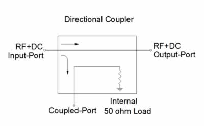
Directional Couplers:
A directional coupler is a device that is used for monitoring incident and reflected power levels. Basic RF directional coupler consists of a pair of transmission lines separated by a gap that determines the coupling ratio of the device. Many designs are available in the market. Octave bands are designs that consist of a single pair of transmission line and designs that consist of more than one pair of transmission.
Multi octave Bands:
Are designs where more than one pair of transmission lines are cascaded to obtain
a wider frequency band of operation. These pairs of transmission lines have difference impedance for each section used and can cover bands with up to 60:1 ratio.
These couplers are also called asymmetric taper transmission lines couplers. The taper pair of transmission enables designers to offer couplers that cover frequency bands 1- 60 GHz.
 Main Line Loss Coupler:
Is the total loss in dB of a microwave signal traveling from the input port to the output port of a directional coupler with all the unused ports terminated to 50 ohm.
Insertion Loss:
Is the mainline loss of the directional coupler minus the theoretical loss of the coupler which depends on the coupling ration see table below.
Theoretical Loss of Directional Couplers:
Also called, 'splitting loss' is the non physical loss of the device which is related to the coupling ratio of the coupler.
| Theoretical Insertion Loss Due to Coupling factor (dB) | |||||||
| Coupling (dB) | 3 | 6 | 10 | 20 | 30 | 40 | 50 |
| Coupling Loss | 3.01 | 1.2560 | 0.4560 | 0.0436 | 0.0043 | 0.0004 | 0.00004 |
Frequency Senstivity or Flatness:
Is the measure in dB of how much the coupling will fluctuate over the specified frequency band. Octave bands designers try to center the design at center frequency.
Coupling Ratio:
How much power will be sampled from the input signal to the coupling port.
This ratio is defined by
C(dB)=10 log | Pin / Pc|
where Pin = power at input port
and Pc = power at coupled port.
Any coupler ratio can be achieved but the standard values are 3, 6, 10, 20, 30, 40 dB.