I Q Networks
Microwave I Q Modulators, Single Side Band Modulators.
I Q microwave Demodulators, Quad IF Mixers.
RF, I Q Networks 10 Mhz to 16 Ghz.
Microwave Image Reject Mixers.
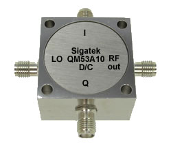
I Q microwave networks modulators and demodulators are the same design devices but are used in a different way based on the application.
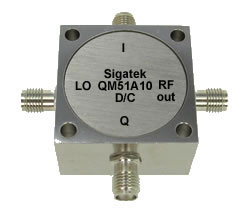
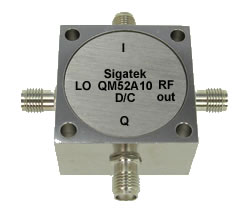
I Q Modulators
An I Q modulator provides an RF modulated output, at the difference and sum frequency of the I Q and LO inputs. The network is composed of one quadrature hybrid (90 degree divider), one 2-way power divider (0 degree divider) and two double balance mixers.
The RF signal is fed to the 0 degree divider and splits before feeding the RF ports of the two double balanced mixers. The LO signal is fed to the quadrature hybrid 90 degree divider and splits with a 90 degree phase shift between the two outputs before feeding the LO ports of the two double balanced mixers. The two IF inputs I and Q of the double balance mixers are combined with the LO frequency from the 90 degree divider to produce the RF modulated-output.
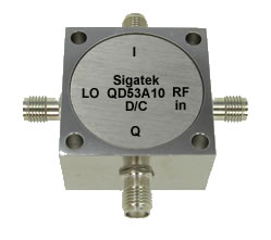
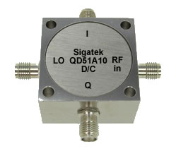
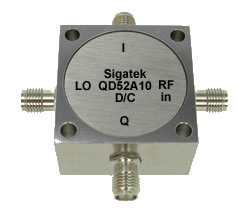
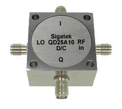
I Q Demodulators
An I Q demodulator provides two equal amplitude and quadrature phase IF outputs I and Q, at the difference frequency of the RF and LO inputs. The network is composed of one quadrature hybrid (90 degree divider), one 2-way power divider (0 degree divider) and two double balance mixers.
The RF signal is fed to the 0 degree divider and splits before feeding the RF ports of the two double balanced mixers. The LO signal is fed to the quadrature hybrid 90 degree divider and splits with a 90 degree phase shift between the two outputs before feeding the LO ports of the two double balanced mixers. The two IF outputs of the double balance mixers provide the IF outputs (I and Q) that are equal in amplitude, but are in phase quadrature.
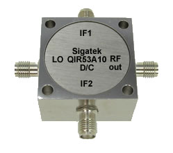
Image Reject Mixers
Microwave Image reject mixers provide high rejection of unwanted signals which are very close to the carrier. RF output is equivalent to the difference and sum frequency of the LO and IF inputs. The network is composed of one quadrature hybrid (90 degree divider) LO side , second quadrature hybrid (90 degree divider) IF side, one 2-way power divider (0 degree divider) RF side and two double balance mixers IF1 and IF2 side.
The RF signal is fed to the 0 degree divider and splits before feeding the RF ports of the two double balanced mixers. The LO signal is fed to the quadrature hybrid 90 degree divider and splits with a 90 degree phase shift between the two outputs before feeding the LO ports of the two double balanced mixers. The two IF inputs IF1 and IF2 is fed to the two double balance mixers IF's ports one at a time where the unused one is terminated to 50 ohms. The output RF is the result of the mixing of LO and IF frequencies.


